WHICH WAY TO POINT YOUR ANTENNA
In the early days of radio control the direction the antenna pointed on the transmitter was predetermined. Early transmitters used valve technology and required a large ground based metal box with a long (5 ½ meter) antenna. There were no options as to the direction of the antenna – they were vertical. As technology evolved transmitters used solid state devices – first transistors then integrated circuits to generate the radio signal. As transmitters reduced in size so too the antenna became smaller – typically 1 meter in length for the 27 MHz, 29 MHz or 36 MHz frequencies used. The antenna still needed to be 5 ½ meters long but by using a centre loaded antenna (a small coil in the middle of the antenna to simulate a longer antenna) a shorter antenna could be used. Finally the transmitter output stage was redesigned to incorporate the coil on the transmitter PCB.
With the solid state transmitters the antenna was mounted vertically on the top of the transmitter however when in use the transmitter was held at an angle so the antenna was neither vertical nor horizontal. Some manufacturers added a gimbal to the antenna to allow the antenna to be oriented in any direction. With modern transmitters operating on 2.4GHz, the antenna only needs to be 62 mm long and most transmitters have an antenna that is able to be positioned in any position. Some transmitters have two antennae one vertical and one horizontal.
So much for the evolution of TX antennae, what about receiver antennae? Aircraft have not changed shape over the years and until the advent of the 2.4 GHz radios the receiver antenna was usually strung from the front of the fuselage to the fin. This resulted in an antenna that was neither horizontal nor vertical. With the 2.4 GHz sets the receiver antenna is only a few centimetres long and can be positioned anywhere in the fuselage in any direction. So what does it matter in which direction the antenna points? Quite a lot and I will try to explain without going into great technical detail. A google search for antenna polarisation will give thousands of responses but they all say the same thing. When a transmitter antenna radiates a radio frequency an electromagnetic wave consisting of two fields is set up - a magnetic field and an electric field – see Fig 1. In general the electric field will be in the direction of the antenna and the magnetic field 90 degrees to it. When talking about the polarisation of an antenna the direction of the electric field is direction of polarisation.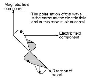
Fig 1 Electriomagnetic Wave.
For maximum signal reception the transmitter and receiver should have the same polarisation. In general, if a transmitter and receiver antenna are rotated so the polarisation changes with respect to each other, there will be a reduction in received signal strength at the receiver. The loss is equal to the cosine of the angle squared. This means for a transmitter and receiver with the same polarisation if the received signal is 100%, for a 30 degree rotation the signal is 75%, for 45 degree rotation the signal is 50%, for 60 degree rotation the signal is 25% and for 90 degree the signal is zero. This is the theory however in practice even when the antennae are 90 degrees apart some signal may be received.
Another thing to consider is the radiation pattern of the antenna. For our transmitters and receivers a dipole antenna is used. The radiation pattern for a vertical dipole can be considered as donut shaped with the antenna in the centre of the hole- see fig 2.
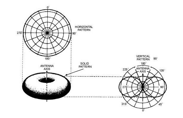
Fig 2 Radiation Pattern
As you can see from the diagram in the horizontal plane the transmitted or received signal is equal in any direction for a given distance from the antenna. However in the vertical plane signal strength decreases as you approach the end of the antenna. Putting all this together you can see that if the transmitter and receiver antennae do not have the same polarisation the received signal strength will be reduced. There will be a further reduction if one antenna is pointing at the other. So for optimum performance the two antennae should be polarised in the same direction and never point at each other.
In practice the way to set up your plane would be to have the transmitter antenna pointed vertically and the receiver antenna pointed vertically. If you have the transmitter antenna horizontal the radiation pattern has a low power area directly off the end of the antenna – remember the donut shape. This means as you face your aircraft the smallest signal is sent to the receiver. If the receiver antenna is vertical there is 90 degrees between the polarisation resulting in subsequent loss of signal.
With a 2.4GHz radio with a single antenna ideally the receiver antenna would be mounted vertically. This is not difficult as the receiver antenna is quite small and it would be easy to position the antenna vertically. Try to locate the antenna as far away as possible from servos and speed controllers as they are a possible source of interference. The transmitter antenna should be positioned vertically and on most modern 2.4GHz sets this is possible. This setup will give maximum coverage – the only thing to remember is, as the aircraft approaches directly overhead both antennae are pointing at each other and there will be a reduction in received signal possibly to the point of loss of signal.
With a receiver with two antennae the instructions with the receiver is to mount the antennae 90 degrees to each other. This does not mean both horizontal with one pointed north south and the other east west rather one vertical and one horizontal. This will give the receiver the maximum signal received as the receiver is smart enough to determine which antenna has the strongest signal and to process the control commands from that antenna. With this setup, as the aircraft orientation changes either rolling, climbing etc the possibility of loss of signal is greatly reduced.
Wikipedia has a detailed article on antenna at:-
https://en.wikipedia.org/wiki/Antenna_(radio)#Polarization